Differentiator of operational amplifier: circuit and its working principle
An operational amplifier (OP AMP) is a linear device that can be used for ideal DC amplification, signal conditioning, filtering and mathematical operations (such as addition, subtraction, integration and differentiation). An operational amplifier is a voltage amplification device with external feedback components, such as capacitors and resistors, between the output and input terminals. The feedback components provided in the operational amplifier can be used to operate effectively. Operational amplifier is a three terminal device, which consists of two high impedance inputs (i.e. inverting input and in-phase input) and an output port. It can be current or voltage. The operational amplifier is mainly used to enhance the low signal level. The operational amplifier differentiator can be active or passive according to the components used in the design.
1、 What is the discriminator of operational amplifier?
Definition: the difference between an operational amplifier is a circuit configuration that produces an output voltage amplitude proportional to the rate of change of the input voltage. This means that when the input voltage signal changes, the output voltage will change immediately.
If the differentiator has only an RC network, it is called a passive differentiator, but if the differentiator has active circuit components such as operational amplifiers and transistors, it is called an active differentiator. Compared with passive differentiator or simple RC differentiator, the active differentiator has lower output resistance and higher output voltage.
Typically, these operational amplifiers are designed to respond to rectangular and triangular input waveforms. If the given input is a sine wave, the output will be a cosine wave with a 90 degree phase shift. If the given input is a triangular wave, the output to be generated is a square wave I. operational amplifier differential circuit
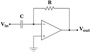
Here, we can see the circuit diagram of operational amplifier differentiator. The circuit uses a capacitor connected in series with the input voltage. Capacitor "C" remains uncharged and acts as an open circuit when the input is DC. In phase terminal grounding. The output is connected to the inverting input terminal through the feedback resistor R1.

The operational amplifier differential circuit performs many mathematical operations, such as addition, subtraction, differentiation and integration. The output voltage generated by the operational amplifier circuit is proportional to the time derivative input voltage. Therefore, it is called a differentiator, and the operational amplifier circuit can also act as a voltage follower.
In the above circuit diagram, if the node voltage at the inverting end of the operational amplifier is zero, the current flowing through capacitor C is:
Iin =If
[If = Vout/Rf]
Capacitor charge equals capacitance and input voltage:
Q = CVin
Therefore, DQ / dt = cdvin / DT, but the current flowing through the capacitor is equal to DQ / dt.
Iin = CdVin/dt =If
-Vout/Rf = CdVin/dt
The ideal output of the operational amplifier differentiator can be written as:
Vout = RfCdVin/dt
Vout = 0 because the amplitude V is constant
For simplicity, assume c1rf = 1
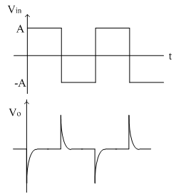
However, in practice, the output is not zero because the stepping wave takes time to rise from 0 to VM volts.
At t = O, the output looks like a spike.
When the input is a square wave, the output waveform will contain positive and negative spikes, which implies the charging and discharging of the capacitor.

2、 Frequency response of ideal differentiator
The gain of the operational amplifier differentiator depends on the frequency of the input signal. When f = 0, the output will become zero in the DC input. When the input signal frequency increases, the output also increases.
At frequency f, the differentiator gain becomes 1.
When the frequency is less than "F", the gain is less than 1.
When the frequency exceeds "F", the gain increases by 20dB every ten times.
3、 Practical operational amplifier differential circuit
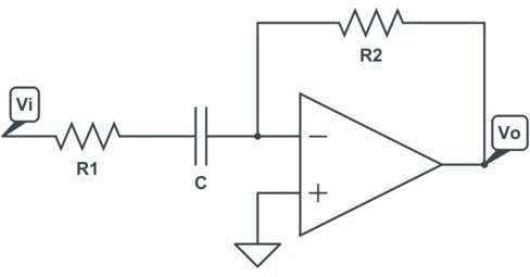
In an ideal differentiator, when the gain is proportional to the frequency. Therefore, the increase of any frequency will lead to the increase of gain, which will lead to the instability of the differentiator at high frequency, so it will produce noise. Here, we can see the circuit diagram of practical operational amplifier differentiator.

The problem can be corrected by the utility circuit, which uses R1 in series with C1 and CF in parallel with RF. The actual circuit output voltage can be written as Vout = RFC1 {D (VIN) / dt}.
Here we can see that the difference between the output voltage and the input voltage is twice RFC1. What happens in this circuit is that at high frequency, capacitor CF and resistor R1 stabilize the circuit, which is very useful to reduce the noise of the circuit.
4、 Frequency response
As we all know, the frequency response of operational amplifier differentiator is directly proportional to the frequency, the gain increases with the increase of frequency, and the gain reaches the unit, that is, it is 0dB at a specific frequency f1. The gain increases at a rate of 20 dB every 10 times until the input frequency reaches F2. In addition to the F2 frequency, the differentiator gain begins to decrease at a rate of 20 dB per 10 times.
This is due to the addition of capacitor CF and resistance R1 in the circuit. This figure shows the frequency response curve of the actual operational amplifier differentiator.


